Thames Water — Chalfont St Peter Deep Manhole Reconnaissance Survey
Project Brief
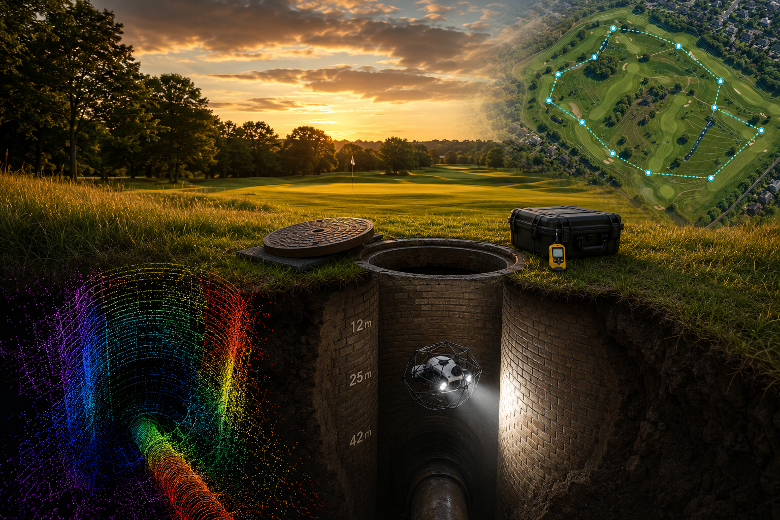
Angell Surveys was approached by a principal contractor tendering on behalf of Thames Water to carry out a reconnaissance survey of ten existing deep manholes on a strategic sewer in Chalfont St Peter, Buckinghamshire. The chambers — ranging in depth from approximately 12 metres to 42 metres — sit on the line of a 675 mm diameter sewer running between them. Most have not been entered in many years, and Thames Water had limited as-built records covering chamber size, internal condition or accurate depths.
The brief was deliberately scoped as a reconnaissance survey rather than the full physical inspection. The downstream contractor needed five things they did not currently have, before they could plan a confined-space entry programme to physically inspect the 675 mm connecting sewer:
- Confirmed X, Y, Z positions of each manhole cover, surveyed to Ordnance Datum.
- A measured internal geometry for each chamber — diameter, shaft type, presence (or absence) of intermediate landings or platforms.
- Accurate depth from cover level to invert.
- A detailed photographic and videographic condition record of the chamber lining, joints, benching, incoming/outgoing pipework and any visible ironwork.
- Confirmation of whether each chamber was a direct-access shaft or contained intermediate platforms — assumed direct-access but not previously verified.
With that dataset in hand the contractor would then design the physical-entry method statement, rescue plan and access logistics for the 675 mm sewer inspection — including the choice of access shafts, ventilation strategy and any temporary platforms needed at depth.
Site Constraints
The manholes are situated across a private members’ golf course outside Chalfont St Peter. Site access conditions were strictly constrained:
- Course access windows agreed with the club’s course manager and limited to non-play periods. Competition days and busy weekends were excluded.
- No vehicle access beyond the maintenance track — all survey equipment carried on foot to each shaft (the manhole positions were spread across multiple holes, with the furthest several hundred metres from any hard standing).
- Battery power only — no generators or external power permitted on the playing surfaces.
- Cover-level finish — every manhole cover sits flush with the fairway or rough. Locations were established from Thames Water’s asset records and verified with GNSS by Angell Surveys on the first day of mobilisation; temporary markers were removed at the end of each visit.
- Working farm-style protocols — no permanent ground disturbance, no marking paint, all kit and waste off-site at end of day.
All ten covers were located, lifted, surveyed and re-secured during agreed access windows — without disrupting play on the course.
Confined-Space Safe System of Work
None of the ten manholes were entered by personnel at any stage of the project. The use of an indoor UAV inspection platform was central to the safe system of work — it removed the need for confined-space entry into untested deep chambers, eliminating the hazards associated with working at depth in atmospheres that had not been characterised in many years.
A site-specific RAMS was prepared and approved by the principal contractor’s safety team before mobilisation. Hazards addressed:
- The potential presence of hydrogen sulphide (H₂S), carbon monoxide (CO) and methane (CH₄) in a foul-sewer chamber environment.
- Oxygen deficiency in deep unventilated shafts that have been closed for years.
- Falling-object risk at the chamber opening during UAV operations.
- Personnel safety adjacent to the open shaft mouth.
Prior to any equipment being deployed at each manhole, a four-gas monitor was suspended on a lowering line and held at progressive depths — 5 m, 15 m, 25 m, 35 m and (where applicable) 42 m — with readings logged at each level before being raised. This atmospheric pre-survey confirmed whether toxic or flammable gases were present at any point in the shaft before the UAV was introduced. Where elevated H₂S or depleted O₂ was logged, additional ventilation time was allowed and the gas survey repeated before the operation continued.
A confined-space rescue standby was maintained at each shaft location, staffed by a trained rescue operative with rescue equipment immediately to hand. A permit-to-work was raised for each shaft, with atmospheric readings recorded on the permit log throughout the operation.
Survey Platform & Technology
The platform selected was a collision-tolerant indoor UAV enclosed within a lightweight carbon-fibre protective cage — the standard tool of the trade for confined-space inspection of deep, unmapped, geometrically variable shafts. The cage allows the aircraft to make controlled contact with chamber walls, ironwork and pipework without sustaining damage or losing control — essential when the brief is precisely to discover the unknown internal geometry.
The aircraft carries:
- A stabilised 4 K ultra-high-definition camera with a wide-angle lens providing a full 180° field of view of the shaft wall.
- An adaptive LED lighting array delivering ~16,000 lumens — enough to illuminate the full internal diameter of a 12–42 m deep chamber at any depth, with dynamic exposure to avoid blowing out the near wall while keeping the far wall properly lit.
- A forward-facing LiDAR sensor and three visual-inertial-odometry cameras feeding a proprietary SLAM (simultaneous localisation and mapping) engine, providing GNSS-denied positional awareness throughout the descent and producing a live 3D point cloud of the shaft interior as the aircraft flies.
The SLAM solution is what makes the survey work as a measured exercise rather than just video reconnaissance. Each chamber’s internal geometry, true depth and the presence or absence of intermediate platforms is captured in the live point cloud, processed back to scaled plan and section drawings for downstream design.
Survey Workflow at Each Manhole
At each of the ten shafts the workflow was the same:
- Locate and confirm the cover position by GNSS against asset records.
- Cordon and signage — set up exclusion zone and welfare area at the shaft mouth.
- Lift cover in coordination with the rescue standby.
- Atmospheric pre-survey — four-gas monitor lowered to graduated depths.
- Photographic and dimensional cover record — frame size, lid type, ironwork condition.
- UAV descent — fully autonomous return-to-signal in event of comms drop-out, live video and 3D map on the ground control station at the surface.
- Internal capture — full 360° photography of the shaft barrel from cover-level to invert, video record, SLAM-based geometry capture, depth confirmation against Ordnance Datum, intermediate-platform check, pipework and benching record.
- Recovery, cover replacement, exclusion zone removal.
Deliverables
For each of the ten manholes Thames Water and the principal contractor received:
- XYZ position of the cover to Ordnance Datum (GNSS-surveyed, sub-30 mm accuracy).
- Measured internal geometry — chamber type, internal diameter, shape, depth from cover to invert.
- Confirmation of platform configuration — direct-access shaft or stepped, with platform elevations where present.
- Photographic condition record — lining material (brick / concrete / sectional), joint condition, ingress/exfiltration evidence, biofouling, corrosion on metalwork, ladder/handrail condition.
- Video record of the full shaft descent and ascent.
- Pipework configuration — incoming and outgoing pipe diameters, invert levels, evidence of the 675 mm sewer connection.
- Plan and long-section drawings of each shaft for incorporation into the contractor’s confined-space entry design.
Outcome
The deliverable pack closed every gap in the principal contractor’s pre-tender information base for the 675 mm sewer inspection: confirmed chamber-by-chamber positions and depths, validated the direct-access assumption (or flagged exceptions), and characterised the condition of the access route to the sewer.
That dataset became the input to the next phase — the design of the physical-entry method statement, ventilation plan and rescue arrangement for the 675 mm sewer inspection — without the contractor having to enter a single untested chamber to gather it. The reconnaissance phase removed the largest unknowns from the programme before any boots went underground.
The project sits in a now-established line of confined-space drone surveys we deliver for principal contractors and asset owners across the UK water and infrastructure industries.
Survey intelligence for modern infrastructure delivery.
Most scoping responses sent within one business day.
RICS-regulated work, led by Philip M. Angell MRICS.