Thames Water — Deep Shaft Chamber Inspection & Survey, Surrey
Project Brief
Angell Surveys was commissioned by Thames Water to carry out a detailed inspection and condition survey of six buried shaft chambers forming part of a strategic water supply asset in Surrey. Each chamber measured approximately 45 metres in depth, with internal diameters varying between 4.5 and 6 metres. The structures had not been inspected in full since original construction and had no existing as-built record of their internal geometry, lining condition, structural jointing, or the configuration of in-service pipework, valves, and access infrastructure within the shafts.
The primary objectives of the commission were twofold: to produce a comprehensive structural condition report for each chamber covering lining integrity, joint condition, evidence of water ingress, biofouling, corrosion of metalwork, and the condition of access ladders and fixings; and to deliver a set of accurate survey drawings of each chamber’s internal geometry — plan, section and elevation — referenced to Ordnance Datum and suitable for use by Thames Water’s engineering team for structural assessment, rehabilitation design, and future maintenance planning.
A further constraint of considerable significance was the location of the chambers. All six shafts were situated beneath the fairways and rough of an active private members’ golf course, with chamber covers set flush to the playing surface and no vehicle access to the shaft locations across the course. The nearest hard-standing access point was approximately 250 metres from the closest shaft. This ruled out any conventional inspection approach requiring heavy lifting equipment, scaffolding erection, or sustained surface plant presence over the shaft covers.
Site Access & Constraints
Working within an active golf course imposed strict operational constraints on every aspect of the project. Access to each shaft was arranged in coordination with the club’s course manager and was restricted to windows agreed in advance to avoid interference with scheduled play. On competition days, certain shaft locations were inaccessible entirely. All equipment was transported to each shaft by hand across the course, with no vehicle access permitted beyond the maintenance track. Each day’s mobilisation required survey personnel to carry all equipment — drone systems, gas monitoring instruments, safety rescue kit, survey equipment, and ancillary materials — on foot to the shaft locations, with the full operational footprint at each shaft limited to a small working area immediately around the chamber cover.
The flush-mounted covers were located using asset records provided by Thames Water and verified against a site plan survey carried out by Angell Surveys prior to the inspection programme. Cover locations were confirmed by GPS and marked temporarily during each inspection visit, with all surface markings removed on completion of each day’s work to leave the course surface undisturbed.
The remote locations and the absence of mains power required the entire operation to run from battery-powered equipment throughout. No generators or external power sources were used at any shaft location.
Confined Space Safe System of Work
All six chambers were classified as confined spaces under the Confined Spaces Regulations 1997. None of the chambers were entered by personnel at any stage of the project — the use of an indoor UAV inspection platform was central to the project’s safe system of work, eliminating the requirement for confined space entry entirely and removing the hazards associated with working at depth in an oxygen-depleted or contaminated atmosphere.
A site-specific risk assessment and method statement (RAMS) was prepared and approved by Thames Water’s safety team prior to mobilisation. The RAMS addressed the specific hazards present at each shaft: the potential presence of hydrogen sulphide (H₂S), carbon monoxide (CO), and methane (CH₄) in a water infrastructure context; oxygen deficiency in deep unventilated shafts; the risk of falling objects at the shaft opening during UAV operations; and the management of equipment and personnel in proximity to a 45-metre open shaft.
Prior to any equipment being deployed at each shaft, a four-gas monitor was suspended on a lowering line to a series of depths — at 5m, 15m, 25m, 35m and 45m — with readings logged at each level before being raised. This pre-inspection atmospheric survey confirmed the presence or absence of toxic or flammable gases at each zone of the shaft before the UAV was introduced. Where gas readings indicated elevated H₂S or depleted oxygen at depth, additional ventilation time was allowed and the atmospheric survey repeated before the operation proceeded.
A confined space standby and rescue arrangement was maintained at each shaft location for the duration of the inspection, staffed by a trained confined space rescue operative with rescue equipment immediately to hand. A permit-to-work was raised and authorised for each individual shaft inspection, with atmospheric monitoring recorded on the permit log throughout the operation. A hot-work exclusion zone and exclusion barrier were established around each shaft opening during UAV operations.
Survey Platform & Technology
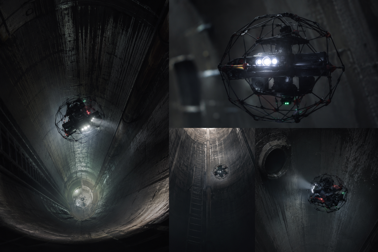
The inspection and survey platform selected for this project was a collision-tolerant indoor UAV enclosed within a lightweight protective carbon-fibre cage. The cage design allows the aircraft to make controlled contact with shaft walls and structural features without sustaining damage or loss of control — an essential characteristic in the confined, irregular geometry of a 45-metre deep brick and concrete lined shaft where maintaining precise separation from the shaft walls at all depths is not always possible.
The aircraft carries a stabilised 4K ultra-high-definition camera with a wide-angle lens providing an unobstructed 180-degree field of view, and an onboard adaptive LED lighting array delivering 16,000 lumens, sufficient to illuminate the full internal diameter of the shafts at all depths. The lighting system automatically adjusts brightness to avoid overexposure on the near shaft wall while maintaining sufficient illumination of the far wall and structural features — critical for consistent image quality throughout the 45-metre descent.
Navigation within the shafts was achieved entirely without GPS using a proprietary simultaneous localisation and mapping (SLAM) engine, combining a forward-facing LiDAR sensor, three visual-inertial odometry cameras, and onboard processing to provide real-time positional awareness and live 3D point cloud generation throughout the flight. The operator monitored the live 3D map, video feed and flight telemetry on a ground control station at the surface, with a smart return-to-signal function enabling the aircraft to autonomously retrace its flight path and return to the shaft opening in the event of communications degradation at depth.
The aircraft’s small footprint — less than 400mm across the cage — and the ability to operate from within the shaft opening without requiring any rigging, rope access, or supporting scaffold made it the only viable platform for this project given the site access constraints. The entire operational setup at each shaft — from cover removal to aircraft recovery and cover reinstatement — was completed within a controlled area of less than three metres diameter.
Survey Methodology
Each shaft was surveyed over a minimum of two flights: an initial descent survey for condition assessment and imagery capture, and a second dedicated survey flight optimised for photogrammetric coverage to support 3D modelling and as-built drawing production. Where shaft geometry or lining condition warranted additional coverage — for example, around inlet and outlet pipe penetrations, at changes in shaft diameter, or where structural defects required close-range documentation — further targeted flights were carried out before moving to the next chamber.
Condition survey flights: The aircraft descended in a controlled helical pattern from the shaft head to the invert, with the camera oriented to capture the full circumference of the shaft lining at regular vertical intervals. The pilot systematically rotated the aircraft to face all quadrants of the shaft wall at each depth increment, capturing overlapping imagery of the lining, construction joints, pipe penetrations, access ladder and fixing condition, benching or sump configuration at the base, and any evidence of cracking, spalling, joint displacement, water ingress staining, biofouling, corrosion, or structural deterioration. Where defects were identified, the aircraft was manoeuvred to within close proximity to document the defect in detail — brick displacement, mortar loss, joint opening, active seepage, and metalwork corrosion were all recorded at sufficient resolution for condition grading in the inspection report.
Photogrammetric survey flights: The photogrammetric data capture flights were planned to achieve a minimum of 80% image overlap in both the vertical and circumferential directions throughout the full depth of each shaft. The aircraft flew a series of descending helical passes at a constant offset from the shaft wall, with camera orientation, speed and rotation rate controlled to achieve consistent image geometry for subsequent photogrammetric processing. Additional nadir and oblique passes were flown at the shaft head, at changes in internal diameter, and at the base to ensure complete coverage of horizontal surfaces that would not be captured by wall-facing imagery alone.
The LiDAR-derived SLAM point cloud, generated live during each flight, provided an initial 3D geometry dataset for each shaft immediately upon recovery of the aircraft. This was reviewed on-site before moving to the next chamber to confirm coverage and identify any geometry gaps requiring a supplementary flight before the shaft was closed.
At the surface, a total station and GNSS survey was carried out at each shaft location to establish the cover level and shaft head position in the national coordinate system (OSGB36, Ordnance Datum Newlyn). These surface control observations tied the internal shaft surveys to the national grid, enabling the as-built drawings to be positioned and levelled in relation to the surrounding infrastructure and other asset records.
Photogrammetric Processing & 3D Modelling
Following completion of fieldwork, the imagery and LiDAR point cloud data from each shaft were processed through a dedicated photogrammetric pipeline:
Image quality screening: Every image captured during the photogrammetric flights was assessed for sharpness, exposure and overlap. Images affected by motion blur during aircraft manoeuvres, or overexposed due to proximity to the lighting array, were excluded before processing. A minimum image set of 85% of captured frames was retained for each shaft.
Feature matching and sparse reconstruction: Scale-invariant feature detection was run across all retained images to extract tie points from overlapping image pairs. The cylindrical geometry of the shafts required careful configuration of the matching parameters — standard overlap assumptions developed for aerial survey do not apply in a vertically oriented cylindrical environment, and the matching was configured to account for the radial image geometry and the 360-degree circumferential overlap between adjacent helical passes.
Bundle adjustment and georeferencing: The photogrammetric block for each shaft was georeferenced using the surface control observations tied to OSGB36. Internal shaft control was supplemented by the SLAM-derived point cloud, which provided an independent check on the photogrammetric reconstruction geometry at depth. Bundle adjustment residuals were inspected and the adjustment accepted only when reprojection error across tie points was below 1.0 pixels RMS throughout the full depth of the shaft.
Dense image matching: Multi-view stereo dense matching was run across the full image block for each shaft to generate a dense photogrammetric point cloud at a mean density exceeding 200 points per square metre across the shaft lining surface. The resulting point cloud provided sub-centimetre surface detail, resolving individual brick courses, joint lines, crack widths, pipe flanges and access rung positions.
Point cloud fusion: The photogrammetric dense point cloud and the LiDAR SLAM point cloud were registered and fused for each shaft, with the LiDAR data used to supplement coverage in zones where photogrammetric reconstruction was less reliable — typically at the very base of the shaft, in the shadow zones behind ladder stanchions, and at the immediate shaft head where the lighting geometry was less controlled. The fused point cloud provided a complete, seamless 3D model of the full internal geometry of each shaft from cover level to invert.
Surface modelling and drawing extraction: A 3D mesh model was generated from the fused point cloud for each shaft, from which plan views, longitudinal sections and developed elevation drawings were extracted at true scale. Internal diameters, construction joint spacing, pipe penetration positions and invert levels were measured directly from the point cloud to sub-centimetre precision.
Condition Assessment
The condition report for each chamber was structured in accordance with the Water Research Centre (WRc) Sewer and Water Main Inspection Manual and Thames Water’s asset inspection requirements, adapted for shaft geometry. Each shaft was assessed and graded across the following elements:
Lining integrity: The full lining surface was assessed for cracking (longitudinal, circumferential and diagonal), spalling, brick displacement, mortar loss, and joint deterioration. Crack widths were estimated from the photogrammetric imagery against a reference scale embedded in selected frames. Active seepage locations were identified and their relationship to construction joints and external features recorded.
Construction joints: All visible ring joints and longitudinal joints were inspected for opening, displacement, and loss of joint filler. Joint condition was graded from Class 1 (sound, no action required) to Class 4 (severe deterioration or displacement, immediate structural review required).
Pipe penetrations: All inlet, outlet, overflow and bypass pipe penetrations were inspected for lining condition around the penetration collar, evidence of root intrusion, grout loss, and pipe displacement relative to the shaft wall. Pipe diameters, invert levels and orientations were measured from the point cloud.
Access infrastructure: Shaft access ladders, step-irons, safety hoops and associated fixings were inspected for corrosion, section loss, cracked welds, missing fixings, and overall structural adequacy. All metalwork was graded against a standard corrosion condition scale, with fixings assessed for load-bearing adequacy.
Benching and invert: The base configuration of each shaft — whether benched, sumped, or open channel — was recorded in plan and section from the photogrammetric model. Invert levels were measured and compared with asset records. Evidence of sediment accumulation, biofouling, erosion or structural deterioration at the invert was noted and graded.
Groundwater ingress: The location, estimated flow rate and spatial distribution of all active and historic water ingress points were recorded and mapped onto the developed elevation drawing for each shaft, enabling the engineering team to correlate ingress with external drainage features, joint positions and depth to groundwater.
Deliverables
Condition Reports (6 No.): Individual inspection report for each shaft, structured to WRc inspection standards, containing: executive summary, shaft identification data, atmospheric monitoring records, photographic evidence schedule (annotated high-resolution images for all defects and significant features), element-by-element condition grading, overall structural condition grade, prioritised maintenance and repair recommendations, and a risk-ranked action register.
As-Built Survey Drawings (6 No. shafts, 4 sheets per shaft): Full drawing set for each shaft in AutoCAD DWG and PDF, comprising: plan at shaft head level, longitudinal section (full 45m depth), developed internal elevation (unfurled 360° lining elevation at true scale), and detail sheets showing pipe penetrations, invert configuration and access ladder arrangement. All drawings referenced to OSGB36 / Ordnance Datum (Newlyn), with internal levels confirmed against surface GNSS control.
3D Mesh Models (6 No.): Georeferenced 3D mesh model of the full internal geometry of each shaft, delivered in OBJ and RealityCapture format, for use in asset management systems and future inspection planning.
Fused Point Clouds (6 No.): Registered and georeferenced LAS point clouds combining LiDAR SLAM and photogrammetric dense match data for each shaft, suitable for integration into Thames Water’s GIS and for direct measurement by the engineering team.
Photographic Evidence Register: Full indexed image library for each shaft — all condition survey imagery catalogued by shaft reference, depth, orientation and defect classification, delivered as a structured folder set with cross-reference index to the condition reports.
Atmospheric Monitoring Records: Complete gas monitoring logs for each shaft, recording readings at all depths and time intervals throughout the inspection programme, provided as part of the permit-to-work closure documentation.
Results
All six chambers were inspected and surveyed to the full 45-metre depth without any personnel entering the shafts at any stage. The complete inspection and survey programme across all six chambers was delivered within an eight-day operational programme, working within the site access windows agreed with the golf course management team. No disruption to course play was reported across the programme.
The photogrammetric as-built drawings achieved a dimensional accuracy of better than ±15mm throughout the full depth of each shaft, confirmed by comparison of measured internal diameters and pipe invert levels against independent check observations. The condition reports identified a number of previously unrecorded structural defects across four of the six chambers, including active groundwater ingress through ring joints at depth, significant corrosion of step-iron fixings in three shafts, and localised lining spalling adjacent to pipe penetrations in two chambers. These findings directly informed Thames Water’s rehabilitation programme, enabling the engineering team to prioritise repair scope and prepare accurate bills of quantities for the remediation works tender.
Thames Water’s asset management team confirmed that the combination of georeferenced 3D models, accurate as-built drawings, and structured condition reports provided a level of asset knowledge for these chambers that had not previously existed, and the data has since been incorporated into Thames Water’s asset register and used as the baseline for ongoing condition monitoring.
Services Delivered
- Confined space inspection UAV survey — 6 shafts, 45m depth, no personnel entry
- Confined Spaces Regulations 1997 compliant safe system of work
- Pre-inspection atmospheric survey — H₂S, CO, CH₄, O₂ at 5m depth intervals
- Permit-to-work management and confined space rescue standby
- 4K HD visual inspection — full 360° lining coverage at all depths
- LiDAR SLAM 3D mapping — GPS-denied, real-time point cloud generation
- Photogrammetric dense image matching — sub-centimetre lining detail
- LiDAR and photogrammetric point cloud fusion per shaft
- 3D mesh modelling — georeferenced internal geometry, all 6 chambers
- As-built survey drawings — plan, section, developed elevation, pipe details (DWG + PDF)
- Surface GNSS control survey — shaft positions and cover levels, OSGB36 / ODN
- WRc-structured condition reports — element-by-element grading, defect schedule, action register
- Photographic evidence register — full indexed defect image library
- Atmospheric monitoring records — permit-to-work closure documentation
- Golf course working — hand-carry mobilisation, no vehicle access, zero course disruption